WHAT IS A CHECK VALVE?
- 获取链接
- X
- 电子邮件
- 其他应用
What is a Check Valve?
The valve that is used to prevent backflow in a piping system is known as a check valve. It is also known as a non-return valve or NRV. The pressure of the fluid passing through a pipeline opens the valve, while any reversal of flow will close the valve.
It allows full unobstructed flow and automatically shuts as pressure decreases. The exact operation will vary depending on the mechanism of the valve.
Parts of Non-Return Valve
It consists of the body, cover, disk, hinge pin, and seat ring. In the image below, you can see the parts of the valve.
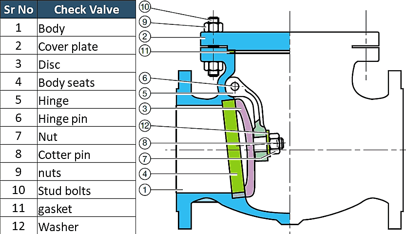
Types of Valves
The type of disk will decide the type of valve. The most common types of Check valves are
- Swing Type.
- Top Hinged
- Tilting disk
- Lift Type
- Piston Type
- Ball type
- Dual Plate Type
- Stop Check Valve
Let’s learn about each of them.
Swing Check Valve
Image – DOE Handbook
The disc in a swing-type valve is unguided as it fully opens or closes. This Valve operates when there is flow in the line and gets fully closed when there is no flow. Turbulence and pressure drop in the valve is very low. Disk and seat designs can be metal to metal or metal to composite.
The angle between the seat and the vertical plane is known as the seating angle and varies from 0 to 45 degrees. Usually, the seat angles are in the range of 5 to 7 degrees. Larger seat angles reduce the disc travel, resulting in quick closing, thus minimizing the possibility of a water hammer. A vertical seat has a 0-degree angle.
The swing-type valve allows full, unobstructed flow and automatically closes as pressure decreases. Usually installed in combination with gate valves because they provide relatively free flow combinations.
A basic swing-type valve consists of a valve body, a bonnet, and a disk that is connected to a hinge.
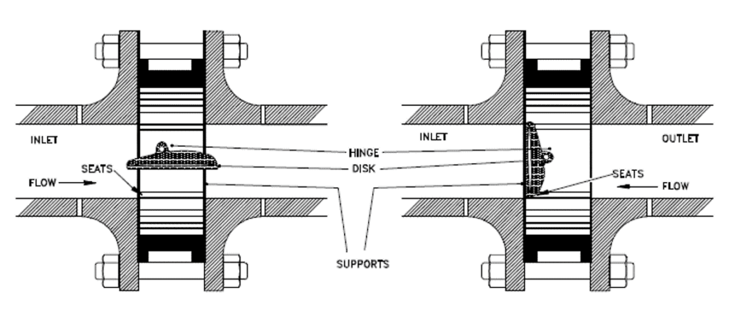
Image – DOE Handbook
The tilting disc-type valve is designed to overcome conventional swing-type valves’ weaknesses. The design of the tilting disk enables the valve to open fully and remain steady at lower flow rates and close quickly when the forwarding flow stops.
The dome-shaped disc floats in the flow and fluid flow on both the bottom and top of the disk surfaces. As the disk is spring-loaded, the spring force helps the valve close fast when forward flow pressure reduces. In the image above, you can see the flow from the valve.
Tilting Disc type Valve is available in wafer type and lug type design.
Ball Type and Plug Type Lift NRV
The seat design of a lift Check valve is similar to a Globe valve. A piston or a ball is usually used as a disk.
Lift Check valves are particularly suitable for high-pressure service where the velocity of flow is high. The disk is perfectly set on the seat with full contact. They are suitable for installation in horizontal or vertical pipelines with upward flow.
When the flow enters below the seat, a disk is raised from the seat by the pressure of the upward flow. When the flow stops or reverses, the backflow and gravity force the disk downward to set on the seat. Commonly used in piping systems that used globe valves as a flow control valve.
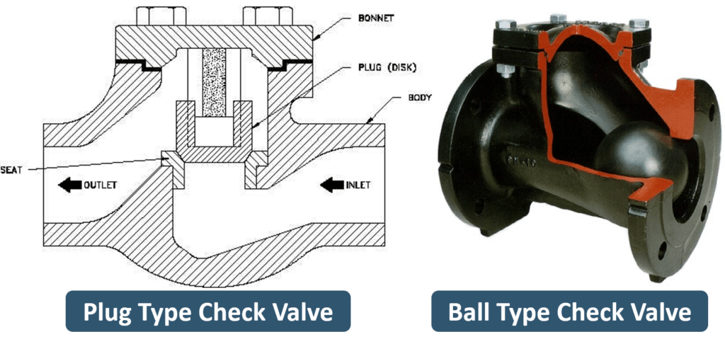
You can see the plug or piston type and ball type check valve here. These valves provide superior leak-tight characteristics to those of swing check valves.
Some design in plug type uses spring to retain the disk in a closed position. This will ensure that the valve allows fluid flow only when there is enough pressure in the flow direction.
A ball-type valve is very simple as it works on the gravity principle. When there is enough pressure in the flow, it lifts the ball upward, but when pressure is reduced, the ball rolls down and closes the opening.
Dual Plate / Dual Disc Check Valve
A dual plate check valve is known as a butterfly check valve, Folding Disc Check valve, double-disc, or splits disc check valve. As the name suggests, two halves of the disk move towards the centreline with the forward flow, and with reverse flow, two halves open and rest on the seat to close the flow (Flapping action).
The use of the Dual Plate Check Valve is popular in low-pressure liquid and gaseous services. Its lightweight and compact construction make it a preferable choice when space and convenience are important.
It is 80 to 90% lighter than the conventional full-body check valve. Frequently used in systems that used butterfly valves. The cost of installation & maintenance is very low compared to other type
Stop Check Valve
Image- DOE Handbook
Stop Check Valve is a combination of a lift check valve and a globe valve. It can either be used as a check valve or as an isolation (stop) valve like a globe valve. These valves can be closed with the help of a stem that is not connected to the valve disc during normal operation, making it possible to use these valves as a regular NRV.
However, the stem is used when needed to hold the free-floating disc against the valve seat, just like a globe valve. These valves are available in tee, wye, and angle patterns. Swing and piston lift valves are commonly used as stop check valves.
Application of Check Valve (NRV)
Check valves (Non-return valves) are used in a piping system to prevent backflow. The rotary equipment’s discharge line, such as the pump and compressor, is always fitted with a check valve to prevent backflow.
Advantages & Disadvantages
Can you guess why I have not mentioned any advantages or disadvantages of the check valve?
The only function of a Non-return valve is to prevent backflow. There is no better alternative. Yes, you can choose the best NRV from the various available type that you have learned, but you cannot supplement the Non-return valve with another valve.
WHAT IS GLOBE VALVE?
A globe valve is a linear motion valve that stops, starts, and regulates fluid flow. The globe valve disk can be removed entirely from the flow path, or it will completely close the flow path. During the opening and closing of the valve, the disc moves perpendicularly to the seat.
This movement creates the annular space between the disk and seat ring that gradually closes as the valve closes. This characteristic provides the globe valve good throttling ability required for regulating the flow.
Leakage from the globe valve seat is less as compared to the gate valve, mainly due to right-angle contact between the disc and seat ring, which allows a tighter seal between the seat and the disc
Globe Valve Diagram
In the below globe valve diagram, you can see how the globe valve functions. The image also shows flow direction.
Image- By Petteri Aimonen
Globe valves can be arranged in such a way that the disk closes against the flow or in the same direction of flow.
When the disk closes in the flow direction, the fluid’s kinetic energy helps close but obstructs the opening. This characteristic is preferable when a quick-acting stop is required.
When the disk closes against the flow direction, the fluid’s kinetic energy obstructs closing but helps open the valve. This characteristic is preferable when a quick-acting start is required.
Globe Valve Parts
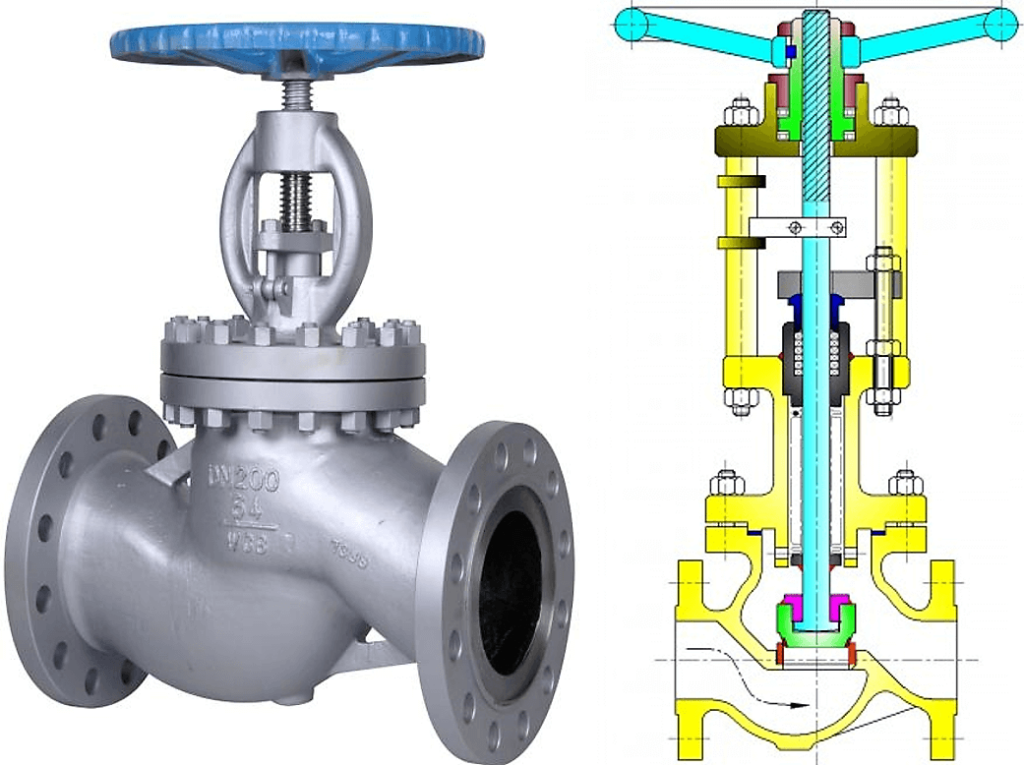
In the image below, you can see the globe valve parts such as Body, Bonnet, Stem, Seat, Disk, etc.
Image- TROUVAY & CAUVIN
Globe Valve Disk Types
Globe valve is available in many different types of disc arrangement. The most used disk designs are listed below.
- Ball Type
- Needle Type
- Composite type
The ball disk design is used in low-pressure and low-temperature systems. It is capable of throttling flow, but in principle, it is used to stop and start the flow.
Needle disk design provides better throttling as compared to ball or composition disk design. A wide variety of long and tapered plug disks are available to suit different flow conditions.
A composition disk is used to achieve better shutoff. A hard, non-metallic insert ring is used in composition disk design.
Types of Globe Valve
Depending on the type of body, there are three types of globe valves;
- Z types
- Y types
- Angle Types
Z types Globe Valve
The simplest design and most common type is a Z-body. The Z-shaped partition inside the globular body contains the seat. The horizontal seating arrangement of the seat allows the stem and disk to travel perpendicular to the pipe axis resulting in a very high-pressure loss.
The valve seat is easily accessible through the bonnet, which is attached to a large opening at the top of the valve body. The stem passes through the bonnet like a gate valve.
This design simplifies manufacturing, installation, and repair. This type of valve is used where pressure drop is not a concern and throttling is required.
Y types Globe Valve
The Y-type design is a solution for the high-pressure drop problem in Z-type valves. The seat and stem are angled at approximately 45° to the pipe axis in this type. Y-body valves are used in high pressure and other critical services where pressure drop is concerned.
Angle types Globe Valve
The angle globe valve turns the flow direction by 90 degrees without using an elbow and one extra pipe weld. Disk open against the flow. This type of globe valve can also be used in the fluctuating flow condition, as they can handle the slugging effect.
Globe Valve Types based on Body Bonnet Connection
Screwed bonnet: This is the simplest design available, and it is used for inexpensive valves.
Bolted-bonnet: This is the most popular design and is used in a large number of globe valves. This requires a gasket to seal the joint between the body and the bonnet.
Welded-Bonnet: This is a popular design where disassembly is not required. They are lighter in weight than their bolted-bonnet counterparts.
Pressure-Seal Bonnet: This type is used extensively for high-pressure, high-temperature applications. The higher the body cavity pressure, the greater the force on the gasket in a pressure-seal valve.
Application of Globe valve
Globe Valves are used in systems where flow control is required, and leak tightness is also important.
- It is used in high-point vents and low-point drains when leak tightness and safety are major concerns. Otherwise, you can use a gate valve for the drain and vent.
- It can be used in Feed-water, chemical, air, lube oil, and almost all services where pressure drop is not an issue.
- This valve is also used as an automatic control valve, but in that case, the stem of the valve is a smooth stem rather than threaded and is opened and closed by the lifting action of an actuator assembly.
Advantages
- Better shut off as compared to gate valve.
- Good for frequent operation as no fear of wear of seat and disk
- Easy to repair, as the seat and disk can be accessed from the valve top
- Fast operation compares to gate valve due to shorter stroke length
- Usually operated by an automatic actuator
Disadvantages
- High head loss from two or more right-angle turns of flowing fluid within the valve body.
- Obstructions and discontinuities in the flow path lead to a high head loss.
- In a large high-pressure line, pulsations and impacts can damage internal trim parts.
- A large valve requires considerable power to open and create noise while in operation.
- It is heavier than other valves of the same pressure rating.
STV is one of the leading China globe valve suppliers focus on the design, manufacturing and supply of various globe valves. We are not only provide high-qualified products but also whole industrial valve solutions.
VALVE TRIM AND PARTS INCLUDING API TRIM CHARTS
A valve is an assembled product. Valve external parts and Valve trim parts such as Body, Bonnet, Disk/wedge, Seat, Stam, Gland Packing / Stud & Bolt / Gasket / Handwheel are all manufactured independently and assembled in a valve factory.
In the image below, you can see the main parts of a valve.
Image – Velan
You can see the cutout of the gate valve. The main components of the valve are listed below.
- Body
- Bonnet
- Stem
- Disk/Wedge
- Seat, Packings
- York
- Bolt
- Sleeves
- Actuator
- Backseat
Let’s learn about each of these parts of a valve.

Valve Body or Shell
The body is the main pressure retaining part and accommodates valve trim. It provides the passage for fluid flow. The body may be cast, forged, or fabricated. Sometimes valve bodies are manufactured by a combination of cast, forged, or fabricated parts. Various metals, alloys, and non-metals are used to manufacture the valve body. The valve body is also known as a shell.
The ends of the valve are designed to connect the valve with pipe or equipment. Ends connections can be a butt, socket, threaded, or flanged type, and sometimes it simply sandwiches between two pipe flanges that are known as wafer ends.
A valve body has different types of passages through which fluid passes. The design of these passages depends on the function of a valve.
- The first body type is Reduced bore; in this type, the passage diameter of the valve is smaller than the connecting This is the most common design as it will reduce overall valve cost and, at the same time it, narrows the fluid flow.
- The second type is a Full bore; in this type, the inside passage diameter of the valve is the same as connecting pipe. This type of body is used when pigging is required. Pigging is used for various purposes, such as cleaning and inspection of the pipeline.
- The third type is Crossflow or Split section body, this kind of body is used mainly in the globe valve, piston, or plug type check valve.
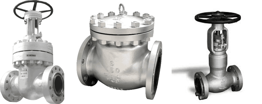
You can see the images of all three types of bodies.
You can now easily work out the difference between the full-bore valve and reducing the bore valve from the above image.
Bonnet or Cover
The cover for the valve body is known as a bonnet. Like valve bodies, bonnets are also available in many designs.
Some bonnets function simply as a valve cover. For example, the swing check valve is shown in the photo. While others support valve internals and accessories such as the stem, disk, and actuator. In the case of the gate, globe, stop check, and diaphragm valves, the bonnet contains an opening for the valve stem to pass through. Usually, a stuffing box is also a part of the bonnet.
Some valves have a bonnetless design in which the valve body and bonnet are combined into one. You can see the bonnetless valve photo. In a split body ball valve, there is no bonnet because the body is split into two sections.
There are many ways to connect a bonnet with a body, such as bolting, threading, and welding. The body-bonnet joint is one of the primary sources of the leak; that is why it should be a pressure-tight. The bonnet is cast or forged of the same material as the body.
What is Valve Trim?
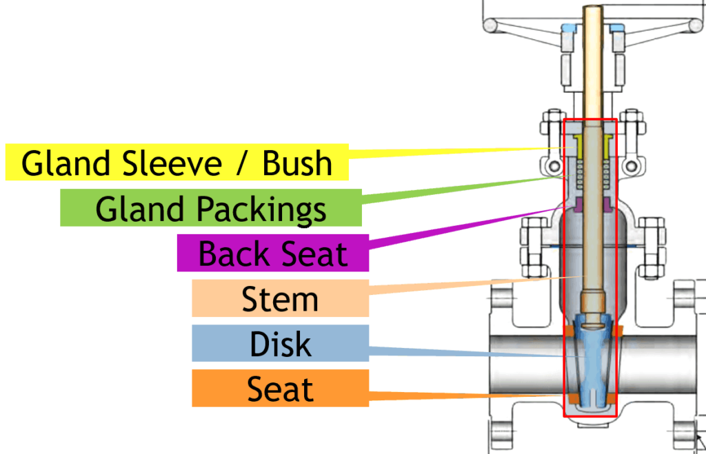
The removable and replaceable internal parts of the valve that come in contact with the flow medium are collectively known as valve trim. Disc, valve seat, and stem are common for all the valves.
Valve Trim components will change with the types of valves. Valve-specific trim includes a back seat, glands, spacers, guides, bushings, retaining pins, and internal springs. Here in the image, you can see the gate valve trim parts. Because of the trim parts, disk movement and flow control are possible.
Disk
The first valve trim part is a disc. The disc is the part that allows, throttles, or stops fluid flow depending on its position. Types of disks define the name of the valve such as gate, ball, plug, and needle valve’s disk are also of the same shape as the name.
A valve disc could be cast, forged, or fabricated. The valve disk is sometimes required hard facing to improve wear resistance. Disk needed smooth machine surface to reduce the friction with a seat. The valve disk is a pressure-retaining part.
That means the disk holds the pressure. When the valve is open, the disc does not perform pressure-retaining or -containing functions. However, when the valve is closed, the disc performs pressure-retaining functions.
A disc rests against the stationary valve seat when the valve is in the closed position. It can be moved away from the seat by the movement of the stem. However, in check and safety-relief valves, fluid flow and pressure move the disc away from the seat.
Seat
The seat provides the seating surface for the disk. Here, you can see the gate valve seat in the above image. A valve may have multiple seats. In the case of a globe valve and swing-check valve, there is one seat. A gate valve and ball valve have two seats; one on the upstream side and the other on the downstream side.
The valve leakage rate is directly proportional to the effectiveness of the seal between the valve disc and seat(s). Valve seats may be integral or replaceable rings. Valves are generally provided with a screwed, welded, or integrally cast or forged seat and hardened by heat treatment or by the hard facing of Stellite weld overlay.
A fine surface finish of the seating area is necessary for proper sealing. Some ball valves & plug valves used the non-metallic seat for non-critical services. Valve manufacturers have developed several designs of combination valve seats involving elastomer and metal seats that are effective in achieving the desired leak tightness, which cannot be achieved only by metal seats.
Back Seat
The back seat is comprised of a shoulder on the stem and a mating surface on the underside of the bonnet. You can see it in the image. It forms a seal when the stem is in a fully open position. It prevents leakage of flow medium to the packing chamber and consequently to the environment. The back seat enables the replacement of the gland packing when the valve is in service
Stem
The stem connects the actuator and disk. It moves and positions the valve disk. The valve stem transports the required motion to the disc, plug, or ball for opening, closing, or positioning the valve. The stem connects the actuator, handwheel, or the lever of the valve at one end and the disc on the other end.
In gate and globe valves, the linear motion of the disc opens or closes the valve, while in the plug, ball, and butterfly valves, the disc rotates to open or shut the valve. Stems are typically forged from stainless steel and connected to the disk by threaded or welded joints.
Bonnet Bolt & Gland Eyebolt
Bonnet bolt or stud, hold the bonnet and body to create a presser tight seal between them. Gland eyebolt serves two functions. First, it connects the gland flange and bonnet. Second, when you tighten the bolt, it pushes the gland bush to retain gland packing in the stuffing box.
York, Yoke Bushing, Yoke Nut
The yoke is also called arms. It connects the valve body or bonnet with the actuating mechanism. The yoke and bonnet are designed as a one-piece construction in many valve designs. A yoke must be sturdy enough to withstand forces, moments, and torque developed by the actuator.
The top of the yoke holds a yoke nut. The valve stem passes through the York. It converts the rotary motion of the actuator into linear motion and moves the valve stem.
Yoke Bushings, also known as stem nut, is an internally threaded nut held at the top of a yoke through which the valve stem pass. Usually, the yoke nut and bush are made of a softer material than the stem to reduce the effort of valve opening. Valves that require greater effort to open or close are provided with anti-freeze yoke-sleeve bearings that minimize the friction between the hardened stem and the yoke bushing.
Non-pressure Retaining Parts of a Valve
Gland Flange is used to provide support to the gland bush to keep the gland packing under tension in the stuffing box.
The Bush or Gland sleeve keeps the gland packing inside the stuffing box.
Stem packing or Gland packing or contained in the stuffing box. Gland packings are made from graphite or PTFE as required by services. Proper compression of gland packing is required to prevent the leak from the stem.
With the help of gland flange and sleeve, you can compress the gland packing. Gland packing is one of the primary sources of fugitive emission in a process plant. Regular maintenance is required to ensure the proper function of packing.
Valve Trim Chart
Trim materials such as disks, seats, stem, back sheet, and sleeves are grouped together and assigned one number called Trim No. or Combination number. This will element the requirement of defining material grade for each component.
- API 600 & 602 gives the list of Trim material that can be used in the valve.
- The most common trim grades are ASTM A410(13Cr), ASTM A316, Alloy 20 (19Cr-29Ni), and Monel (CuNi Alloy).
Here in the image, you can see the simplified chart of the trim material. Against trim number, the seat, disc, backseat, and stem material are specified. This makes it easier to order the valve as you just have to specify trim no based on the requirements and need not specify the material for each of the parts. This list is included in the resource section.
WHAT IS GATE VALVE
Gate valves are primarily designed to start or stop flow, and when a straight-line flow of fluid and minimum flow restriction are needed. In service, these valves generally are either fully open or fully closed.
The disk of a Gate valve is completely removed when the valve is fully open; the disk is fully drawn up into the valve Bonnet. This leaves an opening for flow through the valve at the same inside diameter as the pipesystem in which the valve is installed. A Gate valve can be used for a wide range of liquids and provides a tight seal when closed.

Construction of a Gate valve
Gate valves consists of three main parts.. body, bonnet, and trim. The body is generally connected to other equipment by means of flanged, screwed or welded connections. The bonnet, which containing the moving parts, is attached to the body, usually with bolts, to permit maintenance. The valve trim consists of the stem, the gate, the disc or wedge and the seat rings.
![]()
Cast steel wedged gate valve for oil and gas industry
Disks of a Gate valve
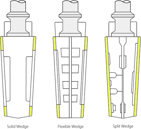
Gate valves are available with different disks or wedges. Ranging of the Gate valves is usually made by the type of wedge used.
The most common were..
- Solid wedge is the most commonly used disk by its simplicity and strength.
A valve with this type of wedge can be installed in each position and it is suitable for almost all liquids. The solid wedge is a single-piece solid construction, and is practically for turbulent flow. - Flexible wedge is a one-piece disc with a cut around the perimeter to improve the ability to correct mistakes or changes in the angle between the seats.
The reduction will vary in size, shape and depth. A shallow, narrow cut gives little flexibility but retains strength.
A deeper and wider cut, or cast-in recess, leaves little material in the middle, which allows more flexibility, but compromises strength. - Split wedge is self-adjusting and selfaligning to both seats sides. This wedge type consists of two-piece construction which seats between the tapered seats in the valve body. This type of wedge is suitable for the treatment of non-condensing gases and liquids at normal temperatures, particularly corrosive liquids.
Most common wedges in Gate valves
Stem of a Gate valve
The stem, which connects the handwheel and disk with each other, is responsible for the proper positioning of the disk. Stems are usually forged, and connected to the disk by threaded or other techniques. To prevent leakage, in the area of the seal, a fine surface finish of the stem is necessary.
Gate valves are classified as either..
- Rising Stem
- Non Rising Stem
For a valve of the Rising Stem type, the stem will rise above the handwheel if the valve is opened. This happens, because the stem is threaded and mated with the bushing threads of a Yoke. A Yoke is an integral part from a Rising Stem valve and is mounted to the Bonnet.
For a valve of the non Rising Stem type, there is no upward stem movement if the valve is opened. The stem is threaded into the disk. As the handwheel on the stem is rotated, the disk travels up or down the stem on the threads while the stem remains vertically stationary.
In the main Menu “Valves” you will find links to detailed (large) drawings of both stem types.
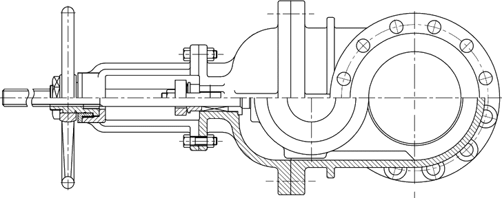
Rising Stem Gate valve
Seats of a Gate valve
Seats for Gate valves are either provided integral with the valve body or in a seat ring type of construction. Seat ring construction provides seats which are either threaded into position or are pressed into position and seal welded to the valve body. The latter form of construction is recommended for higher temperature service.
Integral seats provide a seat of the same material of construction as the valve body while the pressed-in or threaded-in seats permit variation. Rings with hard facings may be supplied for the application where they are required.
Advantages and Disadvantages of Gate valves
Advantages..
- Good shutoff features
- Gate valves are bidirectional and therefore they can be used in two directions
- Pressure loss through the valve is minimal
Disadvantages..
- They can not be quickly opened or closed
- Gate valves are not suitable for regulate or throttle flow
- They are sensitive to vibration in the open state
WHAT IS BALL VALVE?
In order to control liquid flow, a ball valve uses a hollow, perforated, and pivoting ball. The valve is open when the hole in the ball is parallel to the flow inlet; when it is rotated 90 degrees by the handle, it shuts off the flow. It is aligned flat with the flow when it is open and perpendicular to it when it is closed, making it easy to confirm the valve’s status visually. Closed position 1/4 turn can be either clockwise or counterclockwise.
Easy operation, ease of maintenance, and versatility of the ball valve make it ideal for numerous industrial applications. It can support pressures of 1,000 bar (15,000 psi) and temperatures of 752 °F (400 °C), depending on materials and design. Sizes are typically between 0.2 and 48 inches (5.1 and 1,219.2 mm). Metal, plastic, or metal with ceramic valve bodies are common; floating balls are usually chrome-plated for durability.
Ball valves have a high rate of durability, displaying good performance after many cycles, and are reliable, closing securely even after extended periods of disuse. Due to these characteristics, they are frequently chosen over gates and globe valves for shutoff and control applications but are not sufficiently precise for throttling applications.

Working Principle of a Ball Valve
In order to understand how a ball valve works, it is beneficial to understand the five main parts.
Components of a Ball Valve
The ball valve is made up of a valve body that is mounted on a large ball with a center hole diameter equal to the pipe inside diameter. The following figure shows the five main components of a ball valve.
1.Valve stem
2.O-rings
3.Valve housing
4.Ball
5.Seat
The valve stem and ball are connected and can be either operated manually or automatically (electrically or pneumatically). By the ball valve seat and the O-rings around the valve stem, the ball valve is supported and sealed. The valves are all located within the valve housing. Through the ball is a bore. When the stem of the valve is turned a quarter-turn, the bore becomes open, thereby allowing the fluid to flow through or closed, thereby preventing it from going through. The ball valve’s operation is influenced by the circuit function, the housing assembly, the ball design, and the operation type.
Function of a Ball Valve
Using a ball valve, a liquid or gas flow is controlled by a rotating ball that features a bore. A quarter-turn (90 degrees) around the axis allows the medium to flow through or can block it. The valves have a long service life and provide reliable sealing throughout their lifespan, even if it is not used for a long time.
Therefore, they are preferred over the gate valve, for example, as a shutoff valve. Also, they offer superior resistance against contaminated media than most other valve types. A ball valve can also be used as a control valve in some modifications. Because of the limited accuracy of the flow rate control compared to other control valve types, this application is less common. However, there are some benefits to using the valve. It still provides a reliable seal, even if the media is dirty.
Usage of Ball Valves
An oil or gas engineer knows the importance of ball valves in piping systems. They serve various purposes in the oil and gas industry. For example, oil flow is controlled by them in upstream applications. By controlling gas and oil flow, they protect the equipment used in the midstream. Their downstream use is in refining crude oil.
Common Applications of Ball Valves
You can choose from a wide variety of ball valve types and configurations to suit your needs.
- Various fluid services can be managed using ball valves, including on/off stop-valves and bubble-tight shut-off.
- In onshore and offshore upstream oil and gas production facilities, ball valves are the most used fluid shutoff valves.
- Besides hydrocarbon systems, ball valves are equally suited to gaseous, vapor, and air systems.
- Through instrument tubing, ball valves are useful for connecting instruments.
- On fire-truck water delivery parts of the pump, foam systems, and fire-extinguishing systems, as well as in situations where quick action is necessary to open the flow, ball valves are typically found. A ball valve can also be used when two or three valves need to be opened and closed simultaneously.
- Applications with high-temperature and high-pressure conditions can benefit from metal-seated ball valves.
- It’s possible to open and close ball valves quickly, with bubble-tight seals even under high pressure.
Material of Ball Valves
- Stainless steel
- Brass
- Bronze
- Chrome
- Titanium
- PVC
- CPVC
- PFA-lined
The seats and seals used in ball valves also come in many types. Chemical compatibility, pressures, and temperatures determine which applications each are good for. These are some of the materials:
- TMF (valve seat)
- Delrin
- Reinforced Teflon (RTFE)
- Kel F (PCTFE)
- Metal
- Nylon
- PEEK
- Virgin Teflon (TFE)
- UHMW Polyethylene (UHMWPE)
- Graphoil
- Viton
Advantages of Ball Valves
Benefits of ball valves include:
- Using ball valves is easy and cost-effective.
- Ball valves ensure leak-proof service.
- A ball valve opens and closes quickly.
- Ball valves are much smaller than gate valves.
- Ball valves are lighter than gate valves.
- The flow resistance of a ball valve is very low in the fully open position, as compared to that of a gate valve.
- Gate or globe valves do not offer the multi-design flexibility of ball valves, so they require fewer valves.
- Variations in the size and shape of ball valves provide a wide range of options.
- Ball valves of high quality provide safe service in high temperature and high-pressure applications.
- Ball valves require less force to operate than other valves.
- Ball valves do not require lubrication.
Disadvantages of Ball Valves
Ball valves also have some drawbacks, including:
- The ball valve handle position is rotated.
- Throttling cannot be accomplished with ball valves.
- An upright installation is recommended for ball valves with drive mechanisms.
- In closed positions, ball valves trap water in the center cavity when they regulate water flow. When temperatures fall below freezing point, the sides are susceptible to cracking due to ice formation.
- Ball valves are prone to water hammer or surge pressure since they open and close so quickly.
- As the ball moves across the seats with a wiping motion, abrasive solids suspended in the fluid flow may corrode the seats.
It is usually possible to prevent damage in this situation by using insulation and heat tape. Freeze-tolerant ball valves are another alternative in cold climates. It features a freeze plug in the side, which ruptures if the valve freezes up, serving as a ‘sacrificial’ fail point, leading to an easier repair. A new freeze plug can be installed instead of replacing the valve entirely.
FAQ about Ball Valve
- What is ball valve used for?
Using a ball valve, the flow of fluid is controlled by a metal ball that is sandwiched between two seats and contains a hole drilled through its center. Gas and vapors can be controlled by ball valves in hydrocarbon processes and are especially useful in low-flow situations.
- What are advantages of ball valves?
The benefits of ball valves include durability, low cost, shut-off capability, and optimal performance under high accuracy and control demands.
- How long does a ball valve last?
In general, ball valves last 8 to 10 years. This device has enormous value to the gas and water industries despite its simplicity.
WHAT IS A MANUAL BUTTERFLY VALVE?
This is a butterfly valve that is operated using a handwheel or hand lever. A valve operator is needed to start and stop the valve. This valve works by turning the handle which then turns the disc so that it can open or close the fluid flow as necessary. The opening and closing operations need only a quarter turn of the handle a feature that makes these valves quick in operation. These valves are cheaper compared to automatic ones. Manual butterfly valve manufacturers produce this valve using different materials. These materials determine where the valve can be used in terms of temperature and type of fluid that is, corrosive or non-corrosive to viscous fluids. Manual butterfly valves are designed with short lengths which makes them occupy small space relative to other valves. Also, this helps to reduce the weight and cost of the valve. These valves are designed to allow bi-directional fluid flow although there are few of them meant for unidirectional fluid flow.
Figure: Manual butterfly valves.
Components of a manual butterfly valve
Handwheel/hand lever
This is the part of a manual butterfly valve where the operator applies force to start or stop fluid flow. Some of the valves are designed to operate using a handwheel while others use a hand lever.
Body
The body is the main component that houses the internal parts. Manual butterfly valve manufacturer design the body using strong metallic materials such as stainless steel, carbon steel, nickel alloys, and brass among other strong materials. These materials make the body very strong enough to withstand the weight of other components. The high strength also helps the valve withstand fluid pressure as well as protect internal components against falling objects.
Stem
The stem is the part that connects the handwheel/ hand lever to the disc. This component of manual butterfly valve is used to transmit power from the handwheel to the disc. The stem is also made of metallic material to help withstand the torque needed to open and close the valve.
Gear box
This is a component that houses gears used in some manual butterfly valve to change direction of torque from horizontal to vertical. This happens where the handwheel is oriented perpendicular to the stem. The gear box is mounted on top of the valve stem.
Disc
This is the component that is responsible for opening and closing fluid flow through the valve. The disc gets the power to operate from the handwheel through the stem.
Seats
This is a component placed between the disc and the valve body. Seats serve as the surfaces on which the disc rests when the valve is closed. Manual butterfly valve manufacturers design these valves with two seats. The work of the seats is to prevent fluid leakage when the valve is closed.
Gasket
This is a component placed between the valve and pipe connection to prevent fluid leakage. Manual butterfly valve manufacturers design the gasket from various materials. The material used to make the gasket determines where that valve can be used.
Figure: Components of manual butterfly valve.
How does a manual butterfly valve work?
A manual butterfly valve operates when the operator applies torque on the handwheel or hand lever. This helps to either close or open the fluid flow. To open the valve, the handwheel/ hand lever is turned in the counterclockwise direction. This torque is then transmitted to the valve disc through the stem. The disc then makes a quarter turn angle where it aligns itself parallel to the fluid flow leaving the valve open. The fluid then keeps flowing through the open valve. To close the valve, the handwheel/ hand lever is rotated in the clockwise direction for another quarter turn. This torque returns the disc to the seating position. In this position, the disc becomes perpendicular to the fluid flow direction where it blocks any fluid attempting to cross the valve. For throttling fluid flow, the operator turns the handwheel/ hand lever to a certain angle of less than 90o degrees which forces the disc to open slightly allowing some amount of fluid to cross the valve.
Figure: Working of a manual butterfly valve.
Types of Manual butterfly valves
Concentric manual butterfly valve
This valve is also known as a zero-offset manual butterfly valve. This is the most basic type of a manual butterfly valve. Manual butterfly valve manufacturers design this valve such that the stem centerline is collinear to the disc centerline. The disc is placed at the center of the pipe diameter while the seat is in the periphery of the valve body. The disc and seat remain in constant contact. Manual butterfly valve manufacturers design these valves with soft seats that is seats made of plastic or rubber materials. The flexibility of the seat makes the valve to efficiently seal fluid flow when the valve is stopped. Due to the soft seats, this concentric butterfly valve is suitable for use only in low-pressure and low-temperature applications below 60 oC. The media flowing through this valve does not come into contact with the valve body because the seat is made as a sleeve inside the valve body.
Figure: Concentric manual butterfly valve.
Eccentric manual butterfly valve
This valve is also known as a high performance butterfly valve. This valve has the stem passing some distance from the disc centerline. From this design, two types of valves are the double offset type and the triple offset type.
- Double offset manual butterfly valve. This type has the stem axis offset behind the seat centerline and valve body which forms the first offset. The second offset is produced by having the stem offset from the vertical centerline of the valve body. When the valve is started, the seat lifts from the seal which then reduces friction for the first and last 10o degrees of the valve start and stop respectively. Manual butterfly valve manufacturers use this design to enhance smooth operation and tight shut-off. This design also enhances longer life span of the valve relative to the concentric manual butterfly valve. These valves are designed with soft seats which makes them suitable for moderate pressure and low temperatures. For this valve to be used at a higher temperature, the disc is coated with a layer of metallic material. Double offset butterfly valves are used in applications such as HVAC, wastewater treatment, and fire protection among others.
- Triple offset manual butterfly valve. This type of eccentric valve has three offsets. The first two are the same as that of a double offset valve while the third one is a cone axis of the body seal. The third offset is accomplished by use of a right-angled cone profile of the valve seat and a matching profile at the edge of the disc. The use of a third offset helps to reduce disc and seat contact when the valve is closing or opening which then reduces friction. Contact happens when the valve is fully closed. Manual butterfly valve manufacturer design this valve with metal seats. Metallic seats are more rigid and tough relative to rubber or plastic seats. As such, this valve can operate at high temperatures and high pressure. The use of metal seats also helps to reduce wear on the internal parts. Triple offset butterfly valve have long service life relative to the double and the concentric valve types. Manual butterfly valve manufacturers design this valve to work in harsh applications such as corrosive chemicals, superheated steam, high-temperature gases, and liquids among other applications where other manual butterfly valves cannot be used.
Butt-weld manual butterfly valve
This is a manual butterfly valve that is welded to the pipe. This type of valve is used where the piping system is transporting hazardous fluids like corrosives and flammable products. Manual butterfly valve manufacturers design this valve for use where frequent operation is not expected. Also, this valve is suitable for use where high levels of hygiene are not expected since the valve cannot be opened for cleaning while in the field. In case the valve needs some repairs, the weld has to be removed first. These valves guarantee leakage proof between the valve and the pipe which ensures no injuries to the valve operator or to the environment which may happen in other valves that use bolts.
Applications of manual butterfly valves
- Manual butterfly valves are used in petroleum refinery.
- They are used in heating, ventilation, and air-conditioning (HVAC).
- They are used in steam power plants to control the flow of water and steam into and out of boilers.
- Manual butterfly valves are used in mining industries.
- They are used in the manufacturing of various types of chemicals.
- These valves are used in municipal water purification and wastewater treatment.
- Manual butterfly valves are used in food processing because of their ease to clean to enhance hygiene.
- These valves are used in oil and gas processing and offshore pipelines.
- Manual butterfly valves are used in the manufacturing of paper and pulp.
- These valves are used in fire protection.
Advantages of manual butterfly valves
- Manual butterfly valves are cheaper compared to automatic types.
- They are simple and compact in design.
- They need a quarter turn to open and close which saves time and energy.
- Manual butterfly valves are lightweight relative to other valves.
- They serve well in areas with limited space due to their small size relative to other valves.
- They can be bi-directional or uni-directional.
- Manual butterfly valves are easy to install, repair, and clean.
- They are versatile for use in different industries.
- Manual butterfly valves can be used for shut-off or throttling flow.
Disadvantages of manual butterfly valves
- These valves open with the disc in the fluid flow path which reduces fluid pressure.
- Manual butterfly valves may be tedious where high torque or frequent operation is needed.
- These valves have seals that are weak compared to other valves like ball valves.
- Manual butterfly valves are prone to cavitation and choking.
Troubleshooting manual butterfly valves
Valve is hard to operate
- Solid particles clogged in the valve. Open the valve and remove the solid particles.
- Disc and or stem are corroded. Open the valve and remove the corrosion. Clean inside of the valve.
Fluid leakage when the valve is closed
- Dirt inside the valve. Open the valve and clean the dirt.
- Worn out seats. Replace the seats.
- Worn out disc. Repair or replace the disc as necessary.
- Worn out O-rings. Replace the O-rings.
Fluid leakage between the valve and pipe
- Loose bolts. Tighten bolts to the torque recommended by the manual butterfly valve manufacturer.
- High fluid pressure. Verify the fluid pressure level is as recommended by the manual butterfly valve manufacturer.
Summary
A manual butterfly valve is a valve that is operated manually. This valve is operated by use of a valve handwheel or hand lever. The handwheel or hand lever is where the operator applies torque to start or stop the valve. Manual butterfly valve manufacturers design this valve to operate by making a quarter turn angle. The operator turns the handle for a 90o degree angle in the counterclockwise direction to open fluid flow. The handle is rotated in the opposite direction for another quarter turn to close the fluid flow. This valve is also used in throttling fluid flow in which the operator turns the handle for an angle of less than 90o degrees.
Manual butterfly valve manufacturers produce various types of these valves which include concentric manual butterfly valves, eccentric manual butterfly valves, and butt-weld manual butterfly valves among others. Areas of application of these valves include fire protection, mining, water supply, paper and pulp, steam power plants, chemicals, and food processing among others. Advantages of purchasing manual butterfly valves include less expensive, quick operation, small installation space, small in size and light in weight, simple and compact design, and easy to clean, install and repair.
WHAT IS A WAFER BUTTERFLY VALVE?
This is a butterfly valve that is sandwiched between two pipe ends. The pipe ends are in terms of flanges with holes. Long bolts are used to surround the valve body to hold it firmly in its position. The bolts cross the whole valve body. Wafer butterfly valve manufacturers design this valve with or without flange holes on the valve body. Tightly fitted seals such as gasket and O-rings are used between the valves and pipe to enhance leakage-proof connection. Wafer butterfly valve manufacturers produce these valves to operate manually or automatically. The automatic types use actuators to start or stop while the manual types use a handwheel or hand lever. These valves occupy a small space since they are short in length. This property makes the valve light in weight and less expensive. Depending on the material used to make the valve and more so internal components, this valve can be used for low to high temperatures as well as corrosive media.
Figure: Wafer butterfly valve.
Components of a wafer butterfly valve
Body
The body is the component of a wafer butterfly valve that is used to cover internal parts. The body is usually made of strong metallic materials like brass, nickel alloy, stainless steel, and carbon steel among other strong materials. However, other valves are made of plastic bodies and are meant for use in low-temperature and low-pressure applications.
Handwheel/ actuator
Handwheel is the component where the operator applies force to start and stop the valve by making a quarter turn angle. Handwheel is used in manual wafer butterfly valves while the actuator is used in automatic valves. The actuator is designed provide torque to start and stop the valve.
Stem
The stem is the component connecting the handwheel/ hand lever or actuator to the valve disc. The use of the stem is to transmit torque applied on the handwheel or actuator to the disc.
Disc
This is the main component of a wafer butterfly valve as it is used to start and stop fluid flow. It gets the power to open and close from the handle/actuator through the stem.
Seat
A seat is a component used to prevent fluid leakage when the valve is closed. It forms the component on which the disc rests when the valve closes.
Gasket
This component is placed between the valve and pipe mating surfaces to prevent fluid leakage.
Figure: Components of a wafer butterfly valve.
How does a wafer butterfly valve work?
A wafer butterfly valve is classified as a quarter-turn valve. This means that the valve turns the disc for 90o degrees to open or close. Both the actuated and the manual valves have the same working principle. To start the fluid flow, the handwheel is rotated in the counterclockwise direction for a 90o degree angle. This rotation of the handle causes the stem and thus the disc to make the same rotation. As such, the disc becomes oriented collinear to the fluid flow. This leaves the valve open for the fluid to keep flowing. To close the valve, the handwheel is rotated again but in the clockwise direction. This rotation forces the disc to turn and become perpendicular to the pipe where it completely blocks flow through the valve. Wafer butterfly valve manufacturers have designed these valves for both shut-off and throttling use. To use these valves for throttling, the handle and thus the disc is rotated for an angle of less than a quarter turn to allow some level of fluid flow through the valve.
Figure: Working of a wafer butterfly valve.
Types of wafer butterfly valves
Manual wafer butterfly valves
This is a wafer butterfly valve that is operated manually. The manual control mechanism is the handwheel or hand lever and the valve operator applies force to open/close the valve. Compared to the automatic wafer butterfly valve, this valve is cheaper. This valve is suitable for use where electricity or another source of power is not available or would be expensive. Manual butterfly valve manufacturer design some of these valves with a gear system. This design is meant to help change the torque along the horizontal axis to the vertical axis. The torque along the horizontal axis comes from the handwheel and it has to change direction to move vertically downwards to the disc hence the use of the gear system in the gearbox. The gearbox is placed on top of the valve stem. Despite manual wafer butterfly valves being cheaper and convenient to use, they are risky to the operator in case of leakage and hazardous fluids. Also, it may be so tiresome for the operator if a lot of torque is needed where the valve has to start and stop frequently.
Figure: Manual wafer butterfly valve.
Electric actuated wafer butterfly valve
This is a wafer butterfly valve that is operated using an electric actuator. Wafer butterfly valve manufacturers design the actuator with an automated system to help in determining when the disc closes and opens fluid flow. These valves operate using mechanical energy. As such, the valve is designed with an electric motor that converts electrical energy to mechanical energy in terms of torque. The actuator is connected to the valve stem so that it can get the torque needed by the valve. Electric actuated wafer butterfly valves can be installed in all industries because electricity is readily available. However, an electric actuated butterfly valve is expensive compared to the manual one. Repair of the valve is also expensive because of the electrical components like a motor which is expensive to replace. However, the advantages of this valve greatly outweigh the disadvantages since the valve relieves the user of fatigue unlike manual types.
Figure: Electric actuated wafer butterfly valve.
Pneumatic wafer butterfly valve
This is a wafer butterfly valve that operates using a pneumatic actuator. A pneumatic actuator is one that converts energy of compressed air into mechanical energy needed to run the valve. A pneumatic actuator has other names such as air cylinders, pneumatic cylinders, and air actuators. Wafer butterfly valve manufacturers design this valve to rely on compressed air which enters a chamber to build up pressure. Once the pressure exceeds a certain pressure level exceeding the atmospheric pressure outside the chamber, it creates controlled mechanical energy in terms of torque. This pneumatic butterfly valve is versatile as it can be used in different industrial applications involving corrosive and food products. The compressed air can be cleaned before being used to run the valve and thus enhance high levels of hygiene.
Figure: Pneumatic wafer butterfly valve.
Hydraulic wafer butterfly valve
This is a wafer butterfly valve that operates using a hydraulic actuator. The hydraulic actuator operates by using hydraulic liquid. This actuator helps to change hydraulic liquid’s pressure energy into kinetic energy in terms of torque needed to start and stop the valve. This valve is suitable for use where high torque is required since it is more efficient in producing torque because of the incompressible properties of the hydraulic liquid. However, wafer butterfly valve manufacturers recommend use of this valve where there is low temperature since the hydraulic fluid can be affected if the temperature is high. Also, in case the hydraulic fluid leaks, it causes a lot of contamination which is undesirable in industries like foods and beverages and pharmaceuticals processing.
Figure: Hydraulic wafer butterfly valve.
Plastic wafer butterfly valve
This is a wafer butterfly valve that is made of plastic material. There are various plastic materials used by wafer butterfly valve manufacturers to make this valve among them polyvinyl chloride and propylene. This valve is made for use in very corrosive media and which is at low temperatures. Plastic wafer butterfly valve manufacturers recommend this valve in such applications because they are much more resistant to corrosion compared to metallic types like stainless steel. Plastic materials are also cheaper compared the metallic ones. As such, this valve ends up being cheaper compared to the metallic wafer butterfly valves. The design employed to make this valve renders it strong to make it withstand fluid pressure as well as the impact of falling objects.
Figure: Plastic wafer butterfly valve.
Applications of wafer butterfly valves
- Wafer butterfly valves are used in fire protection systems.
- They are used in the manufacturing of chemicals.
- They are used in municipal wastewater treatment and water purification.
- Wafer butterfly valves are used in heating ventilation and air-conditioning (HVAC) systems.
- They are used in the processing of foods and beverages.
- These valves are used in petroleum refineries.
- Wafer butterfly valves are used in mining applications.
- They are used in the pharmaceutical industries as they can easily maintain high levels of hygiene.
Advantages of wafer butterfly valves
- These valves can be automatic or manual.
- Wafer butterfly valves are cheaper compared to other butterfly valves.
- The use of quarter turn to open and close fluid flow makes these valves fast operating.
- Wafer butterfly valves are made of simple and compact design.
- They are of small size and thus light in weight.
- Their small sizes leads to small installation space in the piping system.
- Wafer butterfly valves are easy to clean, install and repair.
- Their design makes them versatile and hence applicable in various industries.
- These valves can allow bi-directional or uni-directional fluid flow.
- They are resistant to corrosion and abrasion wear.
- Wafer butterfly valves can be used in slurries and sludge applications.
Disadvantages of wafer butterfly valves
- Wafer butterfly valve seals are weak compared to other valves which may cause leakage in case of high pressure.
- They contribute to pressure drop because the disc remains in the fluid flow path when the valve is open.
- Their design makes them prone to choking and cavitation.
- The closing and opening of the valve disc is influenced by fluid turbulence.
Troubleshooting wafer butterfly valves
The wafer butterfly valve does not close completely
- Foreign materials in the valve. Open the valve and remove the materials. Clean the internal parts of the valve.
Valve is hard to operate
- Presence of foreign materials in the valve. Open the valve and remove any foreign materials.
- Corrosion in the valve. Open the valve and clean off the corrosion. Ensure the valve is used on the correct type of fluid as recommended by the wafer butterfly valve manufacturer.
External fluid leakage
- Worn out packing. Replace the packing.
- Worn out O-rings. Replace the O-rings.
- High fluid pressure. Reduce the fluid pressure to the range indicated by the wafer butterfly valve manufacturer.
- Loose bolts. Tighten the bolts.
- Worn out gaskets between the valve and the pipe. Replace the gaskets.
Internal fluid leakage
- Worn out seats. Replace the seat.
- O-rings worn out. Replace the O-rings.
- Clogged dirt in the valve. Clean the dirt.
Summary
A wafer butterfly valve is a valve that is installed in a piping system by clamping it between two flanges of the pipe. The pipe flanges are connected using bolts. These bolts cross the valve body to the pipe flanges. Wafer butterfly valve manufacturers design this valve with short lengths which makes it possible for the bolts over the valve. This valve is classified as a quarter-turn valve. This means that the valve operates by turning the disc for a quarter turn angle to start or stop fluid flow. The available designs of these valves operate using handwheel/hand lever or actuator. These valves are applicable in different industries. However, for the best service and economical application, the valve has to be used according to the instruction given by the wafer butterfly valve manufacturer.
Wafer butterfly valves are of various types which include manual wafer butterfly valves, plastic wafer butterfly valves, hydraulic wafer butterfly valves, pneumatic wafer butterfly valves, and electric actuated wafer butterfly valves among others. Applications of wafer butterfly valves include HVAC, wastewater treatment, mining operations, food processing, and chemical manufacturing among others. Advantages of using wafer butterfly valves include lightweight, small size, easy installation, cleaning and repair, fast operation, simple and compact design, and versatility.
WHAT IS A FULL PORT BALL VALVE?
The full-port ball valve is also known as a full-bore ball valve. A full-port ball valve is a type of ball valve with a larger body than a standard ball valve. With a larger body, a full-port ball valve houses a larger ball as well as larger openings. Full-port ball valves have their openings the same size as the connected pipe. For instance, a full port ball valve with a 2-inch diameter will need a pipe of 2-inch in diameter. This means that such a full-port ball valve will have a ball hole of 2-inch. A full-port ball valve is advantageous in that it produces less fluid resistance, pressure drop and has less friction when fluid flows. Full-port ball valves are mostly used in applications where cleaning and low fluid resistance are needed and where pressure loss can affect pipe performance. However full port ball valves are expensive relative to other ball valves.
Figure: Standard port ball valve compared to a full port ball valve.
Components of a full-port ball valve
Valve housing
The valve housing is also known as the valve body. This is the component of a full port ball valve used to cover all internal components of the valve. This is one of the most important parts of a full port ball valve as it protects the valve against excess pressure and safety to all internal parts. The valve housing is made of strong materials relative to its application to ensure that the full port ball valve can withstand high temperature and high pressure.
Valve handle
This is a component used in manual full port ball valves. The handle is the component where the full port ball valve operator applies force to open/close the valve.
Actuator
An actuator is a component used in automatic full port ball valves. The actuator is used to provide the force needed to open/close the full port ball valve. The actuators used in full port ball valves include hydraulic, pneumatic, and electric actuators. An automated system is used to control the closing/opening of the full port ball valve. However, the use of actuators is necessary for complicated control systems.
Stem or shaft
A stem or shaft is the component of a full port ball valve used to connect the ball to the handle or actuator. One end of the stem is connected to the actuator or handle while the other end connects to the ball. The stem has O-rings and packing rings used to prevent fluid leakage.
Rotary ball
This is a ball with a hole at its middle part. The ball is responsible for opening/closing media flow. The ball is connected to the stem so that when the stem is rotated by the actuator or handle, the ball rotates a quarter turn to allow or block fluid flow.
Seats
The seat is a disc installed between the valve body and the ball. The seats help to provide a seal between the ball and the body.
Packing
Packing is a seal placed around the stem. It helps to prevent leakage of fluid through the stem.
How does a full port ball valve work?
A full port ball valve is a ball valve that opens and closes fluid flow using a ball. The ball in a full-port ball valve has a bore at its center. The fluid in a full-port ball valve passes through this bore in the ball. The ball in a full-port ball valve is connected to the handwheel or actuator through the stem. When torque is applied on the handwheel, it is transmitted to the ball via the valve stem. To open a full-port ball valve, the handle is turned a quarter turn that is 90o. When the handle is rotated 90o it also rotates the stem and the ball for 90o. When the ball is rotated for 90o it makes the ball bore to be in line with the pipeline containing the fluid. The makes the fluid flow through the valve and the full-port ball valve is said to be open. To close a full-port ball valve, the handle is rotated in the opposite direction for 90o. This makes the valve stem and the ball rotate 90o. At this stage, the ball bore becomes perpendicular to the pipeline and the fluid cannot flow through the valve. In this state, the full port ball valve is said to be closed.
Figure: Open full port ball valve and closed full-port ball valve.
Types of full port ball valve
Two-piece full port ball valve
This is a full port ball valve with two pieces. One-piece consists of the valve body and one end connection and the second piece is fitted into the first piece to hold the trim in place and it also contains the second end connection. Two-piece full port ball valves can be dismantled for inspection, cleaning, repair, and maintenance. However, in a two-piece full port ball valve, the valve must be removed completely from the pipeline to separate the two pieces. The two-piece full port ball valve is used in high-pressure applications, cold and hot domestic water, HVAC, compressed air, low-pressure steam applications among others.
Figure: Two-piece full port ball valve.
Three-piece full port ball valve
A three-piece full port ball valve is a ball valve designed with three pieces that is a body and two end caps. This full port ball valve has three pieces connected using bolts and nuts. A three-piece full port ball valve is designed in a way that makes it easy to remove the center part containing stem, ball, and seats from the piping system. This helps to enhance effective cleaning of deposited solids, replacement of gland packing and seats, polishing scratches on the ball without the need to remove the pipe from the valve body. A three-piece full port ball valve is advantageous in that it can be serviced without the need to remove the whole valve from the piping system. Three-piece full port ball valves are very strong and thus suitable for high pressure and high-temperature applications. However, three-piece full port ball valves are very expensive relative to other valves like globe valve and butterfly valve.
Figure: Three-piece full port ball valve.
Three-way full port ball valve
A three-way full port ball valve is a ball valve with three ports. This type of full port ball valve uses three ports to serve as a mixing valve or as a diverting valve. A three-way full port ball valve has two configurations that is L shape and the T shape. The L shape of a three-way full port ball valve is used to divert fluid from one port to another port. The T-shaped three-way full port ball valve is used to divert fluid or to mix fluid. When used to mix fluids, a three-way full port ball valve merges two fluid streams from the inlet ports into one stream to flow via the outlet port. T shaped three way ball valve is also used to divert fluid flow from one port into the other two ports.
Flanged full port ball valve
The flanged full port ball valve is a valve defined by flanged ends where bolts and nuts are used to connect the valve to the pipeline. This type of full port ball valve provides effective control of fluid as it can enhance a bubble-tight seal. One advantage of a flanged full port ball valve is that it can easily be removed from the pipeline for inspection, cleaning, repair, and maintenance. As such, this type of full port ball valve can enhance sanitation as it is easy to clean. It is also economical because when a component fails in a flanged full port ball valve, it can be repaired instead of disposing the whole valve.
Figure: Flanged full port ball valve.
Applications of full port ball valve
- Full port ball valves are used in feed water and cooling water systems.
- They are used in irrigation and water supply systems.
- They are used in pharmaceutical industries.
- Full port ball valves are used in steam power generation.
- These valves are used in food and beverages processing.
- Full port ball valves are used in chemical admixtures and treatment.
- They are used in oil and gas industries.
- Full port ball valves are used in fire-safe systems.
Advantages of full port ball valve
- A full port ball valve offers a bubble-tight seal free from leakage.
- Full port ball valves open and close quickly.
- These valves are light in weight relative to other valves like gate valve.
- Full port ball valves are versatile as they can be used in different applications in different industries.
- Full port ball valves are strong which makes them suitable for use in pressure and high-temperature applications.
- The full port ball valve can use multiple ports suitable for different tasks such as fluid mixing and fluid diversion.
- Full port ball valves are suitable for inspection, cleaning, repair, and maintenance.
- Full port ball valves have low fluid resistance which makes them more efficient.
- These valves have a low-pressure drop.
Disadvantages of full port ball valve
- Full port ball valves are not suitable for throttling applications.
- Full port ball valves are not suitable for applications with solids because they tend to cause wear, leakage, and valve failure.
- Full port ball valves are expensive relative to other valves.
Troubleshooting full port ball valves
Internal leakage
- Leakage through the ball. Clogged particles. Clean the particles blocking the ball.
- The stem or shaft is broken. Remove end connection and check rotation of the ball while operating the valve. Repair or replace the stem as necessary.
- Damaged seat. Replace the seat.
- Debris on the seat. Clean the debris.
- Damaged, or displaced seat O-ring. Replace the seat O-ring accordingly.
- Damaged ball. Replace the ball.
The full port ball valve difficult to open/close
- Internal obstructions due to sediment build-up. Remove the full port ball valve and check for sediment build-up and clean the sediments. Check for valve compatibility with the media being worked on.
- Over tightened handle. Loosen the handle slightly.
- Chemical attack on the full port ball valve. Check for an attack such as distortion, etching, peeling, or bleaching of surfaces. Ensure the valve is compatible with the fluid.
- Broken handle. Replace the handle.
- Handle stripped. This could be due to excess exposure to sunlight or high temperature softening the handle. Shield the valve from sunlight. Replace the handle if necessary.
- Broken stem. Replace the stem/shaft.
Summary
A full port ball valve is a type of ball valve in which the diameter of the ball bore is equal to the diameter of the pipe. In this case, for example, a 2-inch diameter ball bore in a full port ball valve will be connected to a pipe with a diameter of 2 inches. Full port ball valves help to reduce fluid flow resistance and pressure drop because the flow is almost straight unlike in other valves such as standard ball valves or reduced bore ball valves. Full port ball valves work by using a ball with a hole at its middle part. The bore is meant to allow fluid flow when the full port valve is open. When a full port ball valve is open, the ball bore is collinear to the pipeline. When the full port ball valve is in a closed state, the ball bore is oriented perpendicular to the fluid flow thus blocking fluid flow.
There are various types of full port ball valves which include three-piece full port ball valve, two-piece full port ball valve, three-way full port ball valve, flanged full port ball valve among others. Full port ball valves are used in various applications among them power generation, feedwater and cooling water systems, oil and gas, irrigation, and chemical industry among others. Full port ball valves are advantageous in various ways such as they can be inspected, cleaned, and repaired, they are versatile, durable, operate quickly, have strong bodies, suitable for high-pressure applications, they are energy efficient among others.
WHAT IS A LOCKABLE BALL VALVE?
What is a lockable ball valve?
A lockable ball valve is a type of ball valve with a lock mechanism. As the name suggests, a lockable ball valve uses a hollow ball and locking mechanism to control fluid flow and lock the valve in an open/closed position. The hole in the valve ball is where the fluid flows through in a lockable ball valve. The lock mechanism is used to ensure valve personnel safety as well as secure the valve in an open or closed state. The lock mechanism covers the stem nut to ensure the lockable ball valve lever cannot be removed which helps to avoid valve interference or tampering. Also, using a lockable ball valve in controlling fluid flow helps to ensure that the valve cannot open by mistake when it needs to be closed and vice versa. Lockable ball valves are important as they help protect people working in pressure relief devices from malfunctions.
Figure: Locking ball valve.
Components of a lockable ball valve
Handle
The handle is the component of a lockable ball valve where the valve operator applies force to open or close the valve. The handle should be made strong enough to withstand the torque required to open the locking ball valve.
Valve housing/valve body
The valve body is the main component of a lockable ball valve which is used to serve as the pressure barrier. This helps to protect the internal components of the lockable ball valve against external damage and holds them tight in position. The valve body is very critical because it needs high strength to make it withstand high pressure.
Stem
The stem is the part of a lockable ball valve that aids in transmitting torque applied by the valve operator on the handle to the valve ball. The stem connects the ball and the handle in a locking ball valve.
Ball
The ball is the component tasked to open or close the locking ball valve. The ball has a hole at its middle part where the fluid flows through. The ball should be made of material that enhances compatibility with the fluid.
Lock mechanism
This is the component of a lockable ball valve which is used to lock the valve in one state that is open or closed state.
Seat
Seats refer to discs used between the body and valve ball in a lockable ball valve meant for providing a seal between the body and the ball and also enhancing ball support against fluid pressure.
Packing
Packing is a component that forms a pressure seal on the valve stem to ensure the fluid does not leak through the locking ball valve.
Figure: Components of a lockable ball valve
How does a lockable ball valve work?
A lockable ball valve is a ball valve with a lock mechanism. The working of a lockable ball valve depends on the ball of the valve. A locking ball valve has a ball with a bore at its middle section. It is the ball that is tasked to open or close the fluid flow. The ball is connected to the handle through the valve stem. To start the lockable ball valve, the handle is rotated for a quarter turn which then rotates the stem and ball at the same 90o angle. In this case, the ball bore becomes in line with the fluid flow from the pipeline which makes fluid flow through the valve. To close the lockable ball valve, the handle is then rotated in the opposite direction for 90o. This then makes the stem and ball rotate for the same quarter turn angle. In this case, the ball bore becomes perpendicular to the fluid flow from the pipeline which makes the valve to be closed. The lock-in of a lockable ball valve is used to close or open the valve when the valve operator finds it necessary.
Types of lockable ball valves
Two-piece lockable ball valve
This is a lockable ball valve with two pieces. One of the two pieces has the body and one connection end while the other piece holds the valve trim and fits into the first piece with its end connection. The two-piece lockable ball valve can be disassembled for inspection, cleaning, and servicing. However, in a two-piece lockable ball valve, the valve must be removed completely from the pipe to separate the two pieces. In most cases, two-piece lockable ball valves have a standard bore or reduced bore ball diameter.
Figure: Two piece locking ball valve.
Three-piece lockable ball valve
A three-piece lockable ball valve is a valve with three pieces that is the body and end caps. The three pieces are held together using bolts and nut connections. The three-piece lockable ball valve is designed such that the central components of the valve that is seats, stem, and ball can be removed easily from the pipeline. This helps to enhance effective cleaning of debris, replacement of gland packing and seats, polishing scratches on the ball without the need to remove the valve body from the pipeline. However, comparing a three-piece locking ball valve to the other valves, this valve is more expensive.
Figure: Three-piece lockable ball valve.
Three-way lockable ball valve
This is a lockable ball valve with three ports. A three-way lockable ball valve can have an L shape or T shape configuration. With an L shape configuration, the lockable ball valve can be used to mix two fluid streams into one stream. The T-shaped lockable configuration of a ball valve can be used as a fluid diverting or fluid mixing valve. When the T-shaped configuration is used as a diverting valve, it is arranged such that the fluid stream from one port is divided into two ports. When the T-shaped configuration of a three way ball valve is used to mix fluids, it combines two fluid streams from two ports to form one fluid stream.
Figure: Three-way lockable ball valve.
Full port lockable ball valve
A full port is also known as a full bore lockable ball valve. This is a valve with its ball bore diameter equal to the pipe diameter. One benefit of a full port locking ball valve is that it does not cause losses due to friction and that the valve can be cleaned easily. When used in large manufacturing systems, the advantage of inspection and cleaning without dismantling the lockable ball valve and without loss of production cannot be underrated. One of the main challenges of a full port ball valve is that the valve body and the valve ball need to be bigger relative to those of a standard lockable ball valve. As such, the cost of a full port ball valve becomes higher. Despite the cost, full port lockable ball valves are useful where low flow resistance is important for example in a pump suction piping system, where pressure loss can lower pump performance.
Reduced port lockable ball valve
A reduced port lockable ball valve is a type of ball valve which has a ball bore diameter less than the pipe diameter. The reduction in ball bore diameter relative to the pipe diameter introduces losses due to friction and turbulence in a locking ball valve. As such, reduced bore lockable ball valves are preferred in cases where turbulence, pressure drop, and material characteristic are not major challenges. A reduced port ball valve is of lower cost and smaller size.
Threaded end lockable ball valve
This is a lockable ball valve that is connected to the pipeline using threads. The threaded connection on a lockable ball valve will be either male or female. A lockable ball valve with a female threaded end connection will need a male threaded pipeline and vice versa. Threaded end lockable ball valves can be disassembled from the pipeline for inspection, repair, and cleaning.
Flanged end lockable ball valve
This is a locking ball valve that has flanged ends for connecting the valve to the pipeline using bolts and nuts. Both the pipeline and the lockable ball valve need flanged ends with holes for the bolts. These lockable ball valves provide a tight seal and they can be dismantled for inspection, repair, and cleaning.
Figure: Flanged end lockable ball valve.
Applications of lockable ball valves
- Lockable ball valves are used in water supply and irrigation systems.
- Lockable ball valves are used in air, liquids, and gaseous applications that need bubble-tight service.
- Locking ball valves are used in feed water and cooling water systems.
- These valves are used in steam services.
- They are used in oil and gas industries.
- Locking ball valves are used in different manufacturing industries.
Advantages of lockable ball valves
- Lockable ball valves provide a lock mechanism when in an open or closed state.
- These valves enhance the safety of valve operators and personnel.
- Lockable ball valves are quick to operate.
- These valves have high strength for high pressure and high-temperature applications.
- Lockable ball valves are versatile as they can be used in different industries.
- Lockable ball valves are small in size and weight.
- Lockable ball valves have a simple and compact design structure.
- A small amount of torque is required to open/close a lockable ball valve unlike other valves like globe valve or gate valve.
- Locking ball valves can be used for fluid mixing and fluid diversion.
- These valves have a perfect seal that prevents fluid leakage.
- Locking ball valves have low-pressure drop and a high fluid flow rate.
Disadvantages of lockable ball valves
- Lockable ball valves can have suspended dirt build up between the ball and the body which can cause erosion, leakage, and valve failure which necessitates frequent maintenance.
- Locking ball valves are not suitable for throttling applications.
Troubleshooting lockable ball valve
Leakage at the thread/bolt connection
- Loose thread connection. Tighten the connection.
- Improper threads. Check threads for proper sizes. Replace the connections if necessary.
- Loose bolts and nuts. Tighten the bolts and nuts.
- Worn out or damaged gasket. Replace the gasket.
Leakage at the stem
- Stem O-ring damaged. Replace the O-ring.
- Broken stem. Replace the stem.
Ball leakage
- Ball obstruction. Check for solids blocking the ball and remove them.
- Damaged ball. Replace the ball.
Leakage through the seat
- Worn out seats. Replace the seats.
- Debris-laden seat. Clean the debris.
- Displaced or damaged seat O-ring. Adjust the seat ring or replace it as necessary.
The handle is difficult to close/open
- Over-tight seal carrier. Loosen the seal carrier slightly.
- Internal obstruction. Disassemble the lockable ball valve and check for segments blocking handle rotation. Clean the segments.
- Broken handle. It could be due to external impact. Replace the handle.
- Broken or sheared stem. This could be due to external impact. Replace the stem as necessary.
Summary
A lockable ball valve is a ball valve with a lock mechanism that can be used to lock the valve when it is in a closed or open state. The lock mechanism is used to help valve personnel to isolate the valve while carrying out valve work which enhances safety in the hope that the valve cannot be used. The ball has a bore at its center which is used to open or close fluid flow. The lock is activated according to the operator’s intended use either in an open or closed state.
There are various types of locking ball valves such as three-piece lockable ball valves, two-piece lockable ball valves, three-way lockable ball valves, flanged lockable ball valves, threaded end lockable ball valves, reduced port lockable ball valves, and full port lockable ball valve. Locking ball valves are used in various applications such as oil and gas, chemical industries, water supply, steam services, air, gaseous and liquid applications among other manufacturing applications. The advantages of lockable ball valves include ease of operation, versatility, high strength for high pressure and high temperature, they have a lock mechanism, and they have perfect seals preventing fluid leakage.
WHAT IS A STEAM TRAP?
Steam Trap is an important component of a steam system. Steam traps have an important role to play in keeping the productivity and reliability of the steam system. The role of a steam trap is to remove condensate, air, and other incondensable gasses from a steam device while not allowing live steam to escape. The need for steam traps, requirements pertaining to their operation, standard modes of operation, troubleshooting, and related requirements are all addressed by this article guide.
Steam Trap
What is a steam trap?
A steam trap is among the family of automatic drain valve that determines steam and condensate. Steam traps hold back steam & discharge condensate under different pressure or loads. Steam traps should have a reasonable capacity to easily expel air and other non-condensable gases while maintaining live steam back. In industries, steam is used daily for healing purposes or as a driving force for mechanical control. Steam traps are being used to ensure that steam is not lost in such applications.
In an official statement, ANSI defines a steam trap as:
“Self-contained valve which automatically drains the condensate from a steam containing enclosure while remaining tight to live steam, or if necessary, allowing steam to flow at a controlled or adjusted rate. Most steam traps will also pass non-condensable gases while remaining tight to live steam.”
Why is a steam trap needed?
In simple words, steam traps are being used to eliminate condensate and non-condensable gasses from the steam system.
Steam is produced as the water vaporizes to change its state to gas. In order for the phenomenon of vaporization to occur, the water molecules should have enough energy to break the bonds between molecules. This energy provided to transform a liquid into a gas is called ‘latent heat.’
The steam produced by the boiler provides the heat energy needed to heat the product. Once steam loses its energy by heating the product in the process, the condensate is formed. A majority of the energy found in steam is often wasted due to radiation leaks from valves and fittings. Since this heat is lost, the steam is condensed and become saturated. If this condensate is not removed instantly as soon as it develops, the operational performance of the device can be minimized by slowing down the heat flow to the phase. If condensate is present in a steam system it will cause physical harm due to water hammering or corrosion.
In the bottom of a horizontal conduit, the condensate is collected with steam moving above it. If the condensate builds up, it will create a dense mass of incompressible water that moves at high speed. As a pipe bend, fitting, or valve abruptly blocks the slug of water, it may cause mechanical damage to the pipe or fitting.
It is similarly important to eliminate air and other non-condensable gasses from the steam system for four critical aspects.
- When the operation is resumed, if the air is present in the system steam is not able to enter, until the air is vented out.
- An air-steam mixture has a temperature far below the steam temperature, which reduces the transmitted heat.
- Air slows-through the heat transfer as it clings to the inside surface of the pipe or vessel.
- Dissolved in condensate, non-condensable acid gasses that corrode the system.
How does a steam trap work?
All steam traps operation can be categorized under one of three fundamental working principles: velocity, temperature, or density. Over time, various types of steam traps have been built to accommodate different applications. The important function of a steam trap is the ability to differentiate between steam and condensate. Various types of steam traps use various operating criteria and methods to differentiate between steam, condensate, and air. When categorized according to these operating principles, each type has advantages and disadvantages which must be addressed when choosing a steam trap for a particular application.
How many different types of steam traps are there?
Steam traps can be divided into two main types owing to their working principles, they are:
- Mechanical steam traps: Mechanical steam traps work on the concept of specific gravity, as compared to other types of steam traps that depend on temperature change or velocity/phase change. In mechanical cages, the valve opens and shuts due to the displacement of a float that rises and falls with a condensate surge.
There are two major designs of mechanical traps: float traps and inverted bucket traps. Float traps generally use an enclosed spherical float, whereas inverted bucket traps use a buoyant, cylindrical cup turned upside down.
Buoyancy is a key element working at the core of all types of mechanical traps, but the mechanisms and operating concepts are a little different.
- Ball float steam trap: It incorporates the effect of both temperature and density. A ball float opens the primary valve as enough condensate reaches the trap to raise the float, discharging the condensate. When the machine drains, the ball drops and the valve shuts down. A separate thermostatic component at the top of the trap gets open for the release of air and non-condensable gases, as soon as they induce a slight temperature drop in the trap.
Ball float steam trap
- Inverted bucket steam trap: It employs an upside-down bucket or an open float, which works on the density difference of steam and water. Steam flowing under the inverted and submerged bucket allows the vapor to float and shut the discharge valve. Condensate filling the trap allows the bucket to sink, releasing the trap valve to remove the condensate. A small vent at the top of the bucket allows the stored air to flow through to discharge the condensate.
Inverted Bucket Steam Trap
- Thermodynamic steam trap: Thermodynamic steam traps are appreciated for their small size and flexibility over a wide range of pressures. They may have a basic construction and work either horizontally or vertically. These properties make thermodynamic steam traps a popular alternative for a wide range of tracing, drip, and light flow steam applications.
There are two basic types of thermodynamic steam traps: thermodynamic disk and thermodynamic impulse (thermostatic steam trap).
- Thermostatic steam trap: The pressure determines the temperature of saturated steam. In the steam chamber, steam loses the enthalpy of evaporation (heat), creating condensate at steam temperature. As a consequence of any more heat loss, the condensate temperature will decrease. A thermostatic trap will allow the condensate to pass when this lower temperature is observed. When the steam enters the trap, the temperature rises and the trap shuts.
Thermostatic Steam Trap
- Thermodynamic steam trap: Thermodynamic traps are the most common type of traps, they are built on the theory of velocity. Condensate and air reach the trap and travel into the gate, heating, and control area. When steam or flash steam enters the entry, the flow speed rises and the disk is pulled towards the seat. The disk is closed with rising pressure in the control chamber. The controlled swelling of vapor pressure over the sealing face of the disk causes the trap to open up again and controls the speed of cycling.
Thermodynamic steam trap
Why are steam traps so important?
It costs money to produce and hold steam for process and space heating in the factory. That is too costly to waste. Steam is taken from a furnace to thousands or hundreds of branches. The steam trap prevents the steam from escaping out of the device at the end of each branch.
If condensate is not extracted, flowing steam and small waves within the pipe can be pushed together with faster-moving steam. The force of the steam behind the plug produces the water lull like the strength of a battering ram, if one of the waves hits the top of the pipe basically plug. This water trick will ram into teas, knees, pumps, floats in some traps, and other device equipment. This behavior can be very damaging and is one of the types of water hammer.
Steam, condensate, and air will share the same space inside a heat exchange unit. As condensate, air, and non-condensable gasses are separated as soon as they are created, the steam has more surface to transmit heat energy. Steam in the presence of water or air is an energy transfer medium that is less effective than dry steam.
What happens if a steam trap blows through?
If the malfunction of a single trap is overlooked, some steam can blow out and be released into the atmosphere. Steam costs an average of $5/1000 lb to produce, thousands of dollars can be lost every year. Current trap surveys have found that the average faulty trap losses 50 lb of steam per hour. The annual loss amounted to more than 400,000 Ib of steam at a rate of $2044. Multiply this by 100 to estimate the scale of a standard steam machine, and minor steam losses begin to add up to real money. Small traps are the secret to saving steam, not because they are vulnerable to collapse, but because there are several of them.
Functionally, a blow-through trap can have effects that extend into its heat exchange system. If the failed trap is attached to the condensate return line in which the other traps are discharged, the unexpected amount of live steam can pressurize the return line, causing backpressure for the other traps. Any steam traps do not work properly under high backpressure. In either case, the elevated back pressure may cause condensate to back up in other parts of the system.
What happens if a steam trap locks shut and Won’t discharge?
When the trap on the steam line fails closed, the closed valve does not allow the steam and condensate to flow through it and accumulates in the line. The condensate continues to move to low spots and collect there, with the ability to partially obstruct the flow of steam and cause a water hammer. If the line is exposed to temperatures below zero, the condensate can freeze and the pipe may be broken.
Some major problems that can be seen are:
- Water Hammer and pressure surge.
- Water Logging in the process.
- Damage to piping and Process equipment.
- Compromise safety.
What makes one type of trap better than another?
It totally depends on the application and operating requirements of a trap that is to be used. It also depends on what is expected from a steam trap to do. Steam traps are commonly used for the following requirements:
- To minimize steam loss.
- To draw maximum output from the heat exchange equipment that is used.
- For a smooth operation that is failsafe and trouble-free.
- Increase the lifespan of equipment present in the system.
- For reliability of operation even under dirty steam conditions.
Where should traps be located?
Accessibility, all traps will crash, and fail. Traps must be tested periodically so that the damaged trap does not waste steam for months or years. The inspection method is made simpler if the trap can be approached effortlessly. Often, a list of the trap positions makes it easy to locate all the traps.
Below the machinery is being drained. Although the heater coil and its steam trap will work at 250 psi steam pressure, the condensate must be pulled into the trap at some point of gravity. With most heat exchangers, the thumb rule is to position the trap inlet at around 10 to 12 inches. Below the relation of the condensate drain. A 6-inch dirt pocket should be given to shielding the trap from dirt and size.
Steam mains need some additional care since high-speed steam makes it difficult to remove the condensate. The drip leg should be adequately designed, the same height as the mainline, up to and above 4 in., use one-half of the mainline size, but not less than 4 in.
Close to the facility being emptied. As noted above, the flow of gravity carries the condensate to the trap. Around the same time, air and steam are being pushed upward through the pipe. To mitigate issues with this counter-flow, stop long pipe runs to the steam trap.
In summary.
Steam traps are safety equipment that is employed to increase productivity and at the same time operation cost of the process is lowered. We have provided a brief introduction to the steam trap in this article. STV is a professional China steam trap manufacturer, please feel free to contact us if you have any questio
- 获取链接
- X
- 电子邮件
- 其他应用
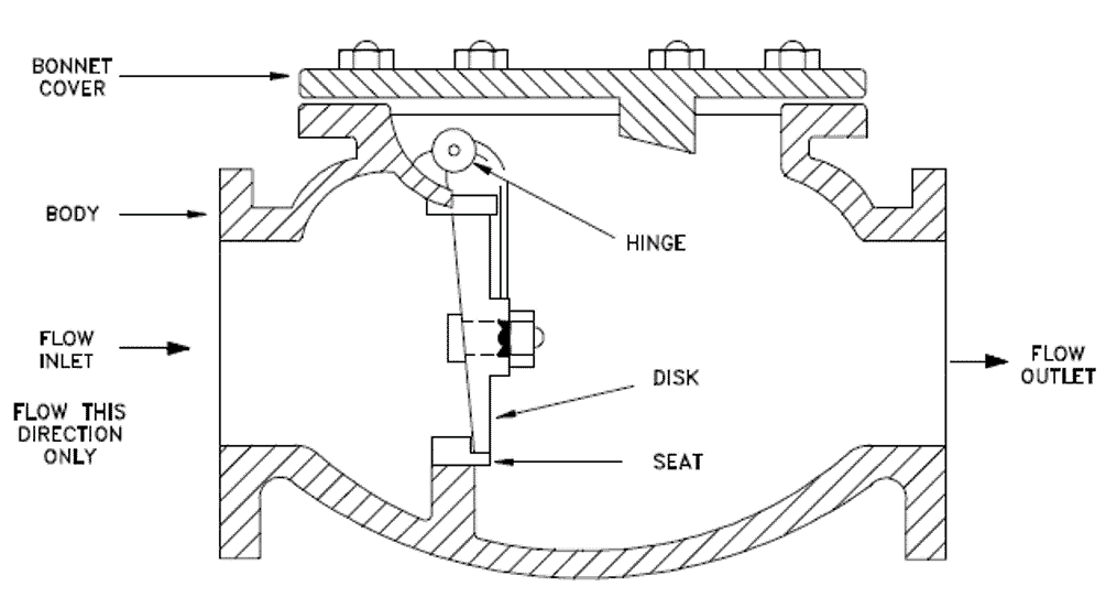
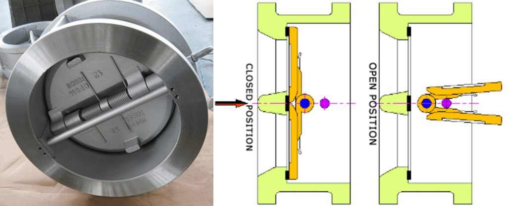
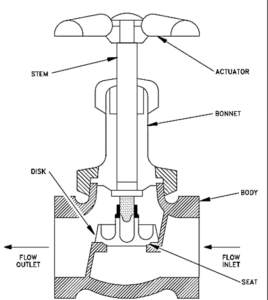
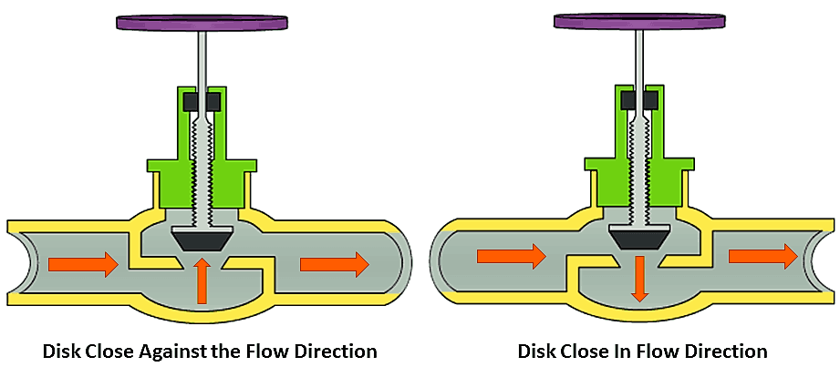
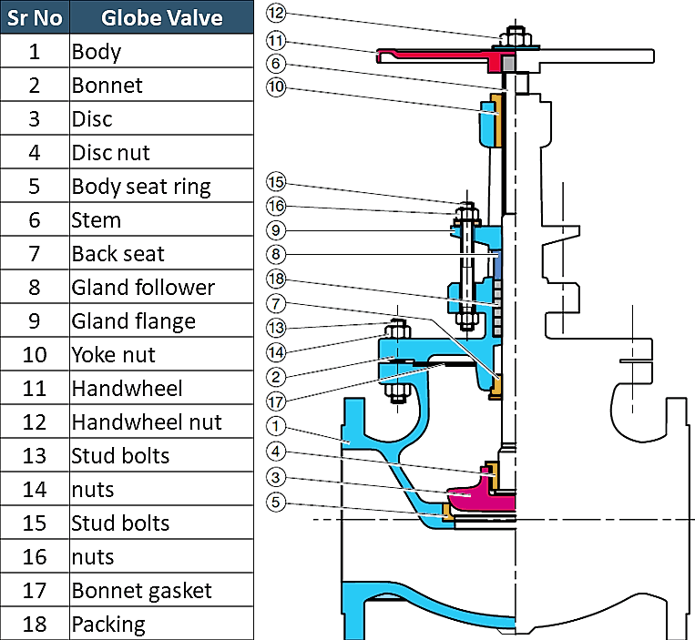
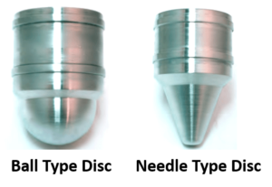
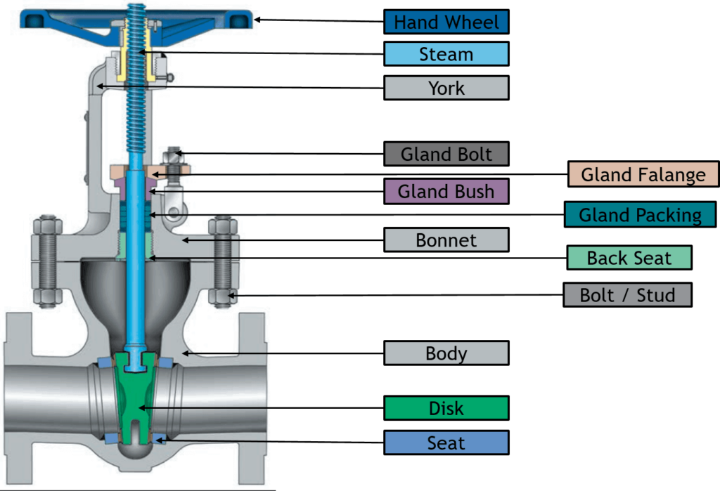
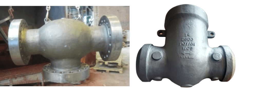
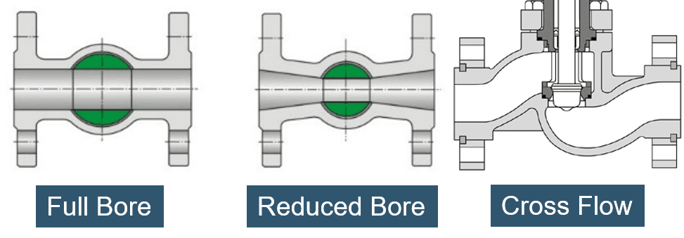
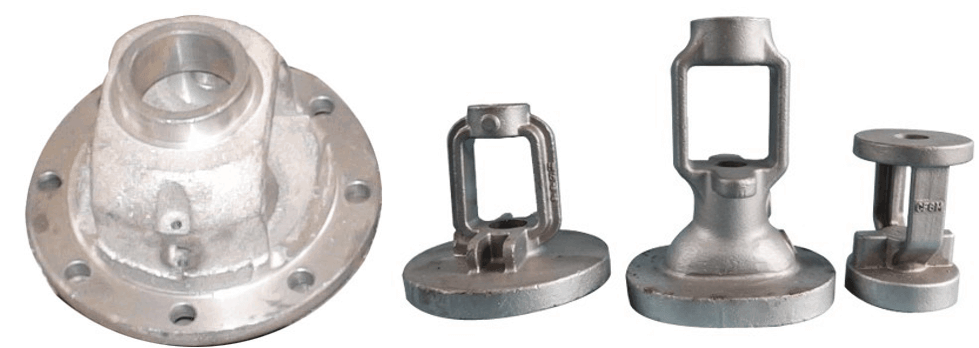
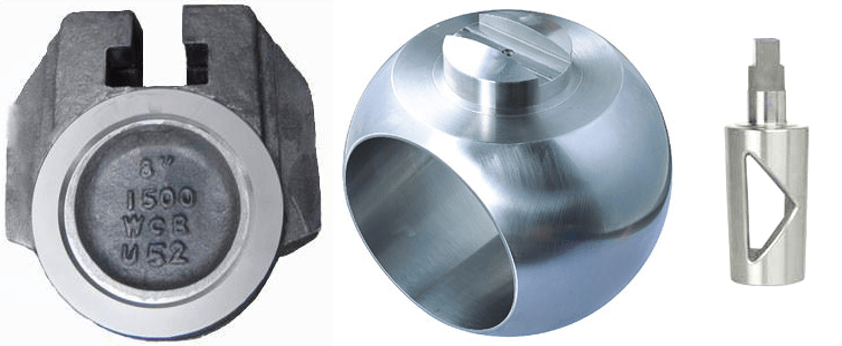
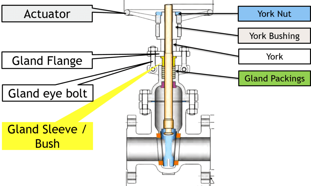
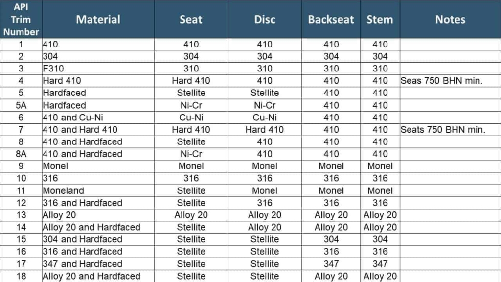


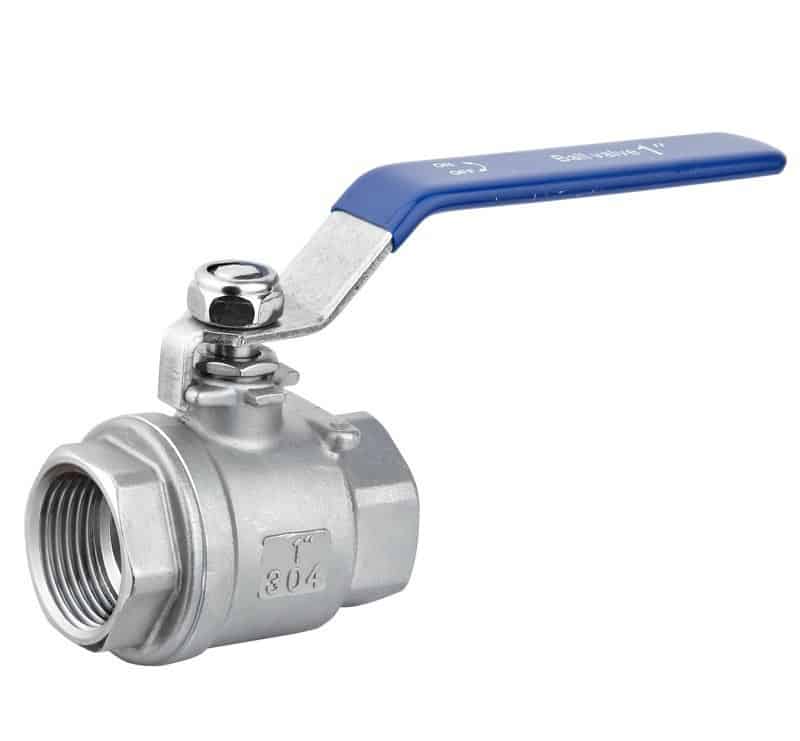
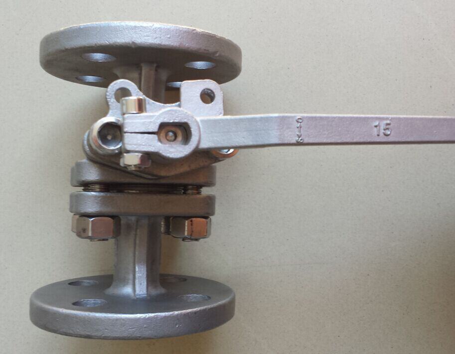
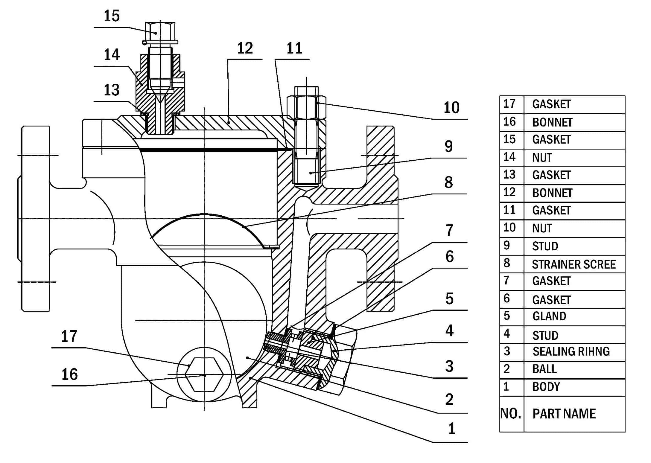

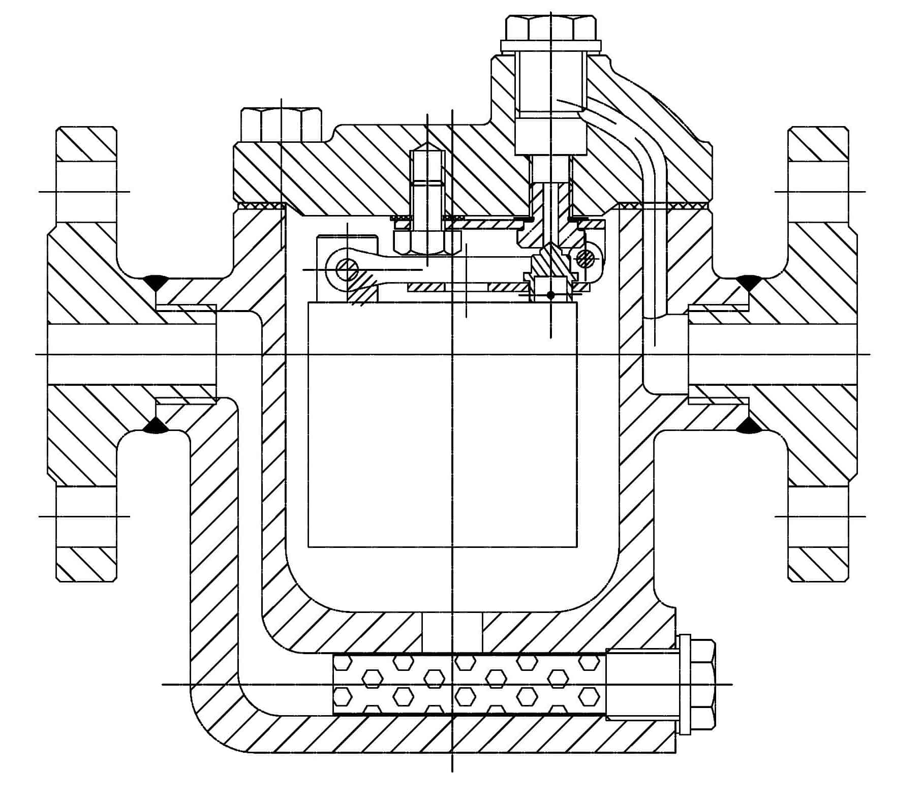
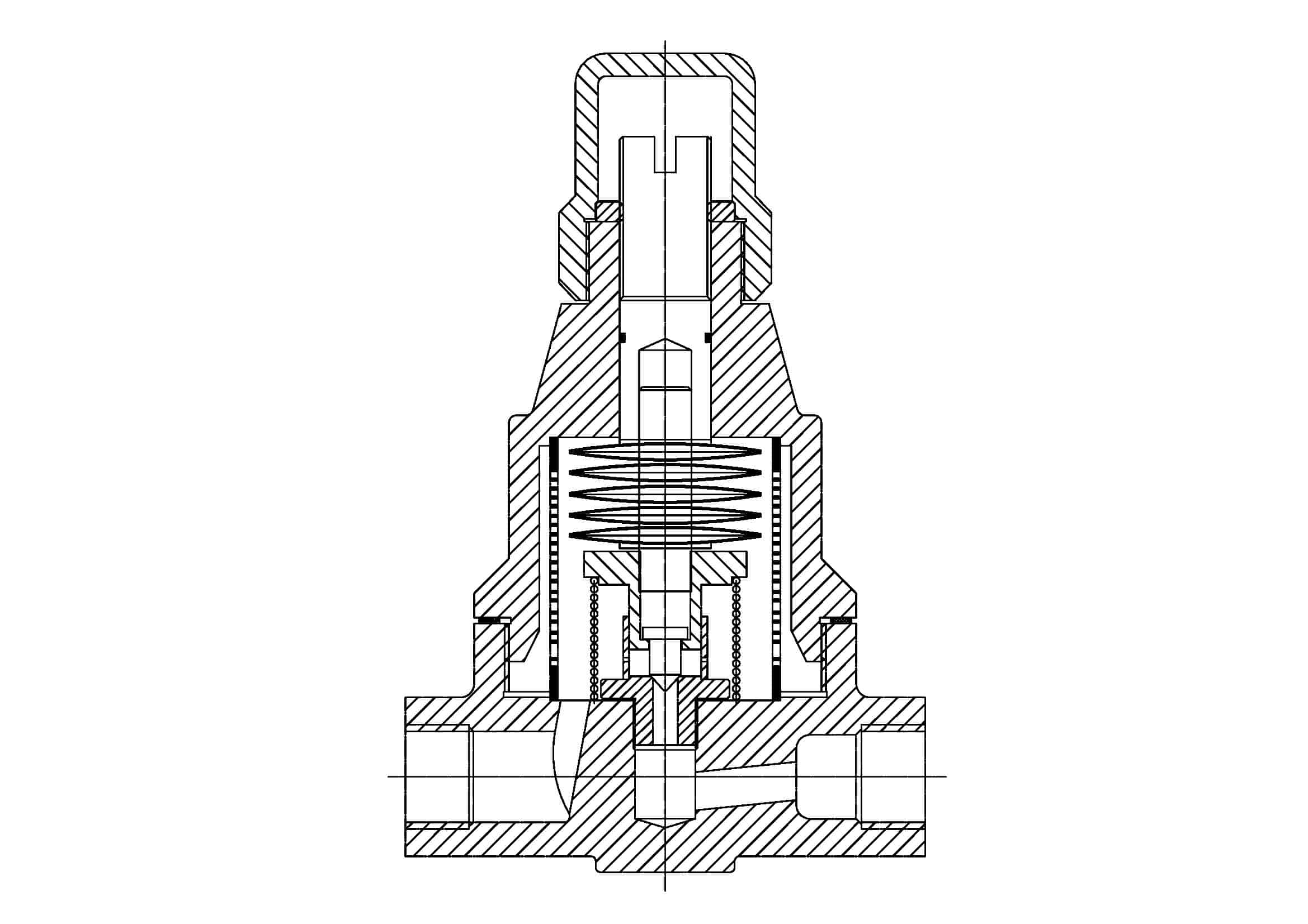
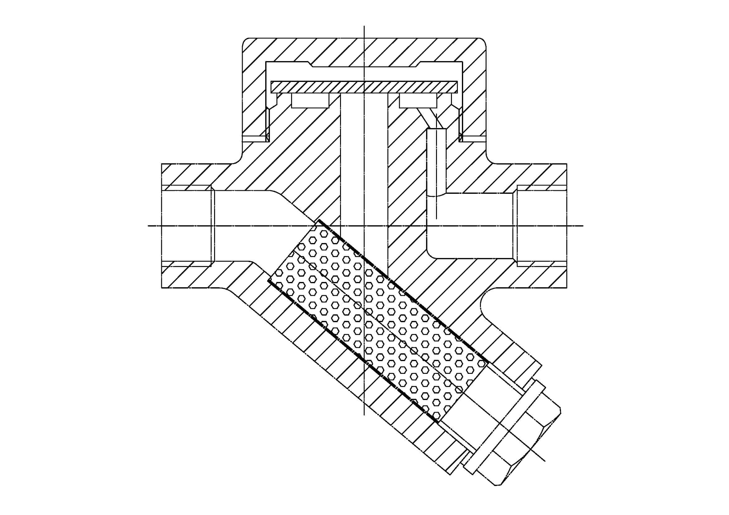
评论
发表评论